Tag Archives: nxp philips

ARM7 to ARM7 (LPC2148) communication using I2C

1 Apr

     Board to board communication using I2C protocol, is simple once you’ve done any other program using this protocol with arm7. Since I have interfaced arm7 with eeprom. The same code used to send data to the eeprom is been used,except for the change in slave address,in this case it’s (0x00);

SEND

Master transmit mode

#include<lpc214x.h>
#include<stdio.h>
#include”appdef.h”
#include”armlcd.h”
#define led_port BIT0+BIT1+BIT8+BIT9+BIT25+BIT15+BIT12+BIT28
int c=1;
int r=0;
static int i=0;
unsigned char buf[12]=”YES YAMAHA”;
__irq void led(void)
{
     IOSET0=led_port;
     switch(I2C0STAT)
     {
         case 0x08 : lcd(‘s’); //start
                             I2C0CONCLR=BIT3+BIT5;

                             I2C0DAT=0x00;  //slave address of the other board

                             break;
          case 0x18 : lcd(‘a’);
                             I2C0CONCLR=BIT3;
                             break;
         case 0x28 : lcd(‘k’);
                            I2C0CONCLR=BIT3;
                            switch(c)
                            {
                               case 1 : I2C0DAT=buf[i];
                                             i++;
                                            if(i==10)
                                            {
                                                c++;
                                             }
                                             break;
                              case 2: I2C0CONSET=BIT4;
                                           lcd(‘p’);
                                           break;
                            }
                              break;
       case 0x30 : lcd(‘n’);
                          I2C0CONCLR=BIT3+BIT5;
                          break;
       default:      lcd(‘f’);
                         break;
}

VICVectAddr=0x00;
}

int main()
{

rs_clr();
en_clr();
lcd_init();
rs_set();
en_clr();
lcd(‘i’);
PINSEL0=BIT4+BIT6;

VICVectCntl0=0x29;
VICVectAddr0=(unsigned) led;
VICIntEnable=BIT9;

I2C0CONSET=BIT6;
I2C0CONCLR=BIT3+BIT2+BIT4;
I2C0SCLH=0x4B;
I2C0SCLL=0x4B;

I2C0CONSET|=BIT5;
while(1);

}
void lcd_init()
{
unsigned int i;
PINSEL0 = 0x00000000;

lcd_dir_write(); // output port
for (i=0;i<1000;i++);
lcd(0x33);
lcd(0x32);
lcd(0x28);
lcd(0x0e);
lcd(0x01);
lcd(0x06);
lcd(0x80);

for (i=0;i<1000000;i++);
}

void lcd(unsigned char val)
{
lcd1(val>>4);
lcd1(val);
}

void lcd1(unsigned char c)
{
unsigned int i;
IOCLR0 = 0x00f00000;
IOSET0 = (c<<20); // d4 connected to 20th port pin
en_set();
for (i=0;i<1000000;i++);
en_clr();
}
RECEIVE

Slight changes at the code at the slave side.You have to choose the arm controller to be in slave mode.

Slave receiver mode.

I2C0ADR=0X01; // general call address.Only when you set bit0 of this register can the master board send address as 0x00 to the slave board.

Enable bit & AA bit of the I2CCONSET register has to set to 1 during initialization. 

Remember no start bit required.

status codes are 0x70,0x90. go through the user manual

#include<lpc214x.h>
#include<stdio.h>
#include”appdef.h”
#include”armlcd.h”
#define led_port BIT0+BIT1+BIT8+BIT9+BIT25+BIT15+BIT12+BIT28
int c=0;
int r=0,dw=1,ss=0,rs=0,j;
char ch;
__irq void led(void)
{
        switch(I2C0STAT)
       {
           case 0x70 : lcd(‘g’);  
                              I2C0CONSET|=BIT2;  //AA bit set
                              I2C0CONCLR=BIT3;
                              break;
           case 0x90 :ch=I2C0DAT;  //data received and stored safely
                             I2C0CONCLR=BIT3;
                             lcd(ch);
                             break;
           case 0xa0 :lcd(‘p’);
                             I2C0CONCLR=BIT3;
                             break;
           default:lcd(‘f’);
                       I2C0CONCLR=BIT3;
                       break;
}

VICVectAddr=0x00;
}

int main()
{

rs_clr();
en_clr();
lcd_init();
rs_set();
en_clr();
PINSEL0=BIT4+BIT6;
VICVectCntl0=0x29;
VICVectAddr0=(unsigned) led;
VICIntEnable=BIT9;

I2C0ADR=0X01;  // general call addr
I2C0CONSET=BIT6+BIT2; // SLAVE MODE
I2C0CONCLR=BIT3;
I2C0SCLH=0x4B;
I2C0SCLL=0x4B;

lcd(‘v’);
while(1);
}
void lcd_init()
{
unsigned int i;
PINSEL0 = 0x00000000;

lcd_dir_write(); // output port
for (i=0;i<1000;i++);
lcd(0x33);
lcd(0x32);
lcd(0x28);
lcd(0x0e);
lcd(0x01);
lcd(0x06);
lcd(0x80);

for (i=0;i<1000000;i++);
}

void lcd(unsigned char val)
{
lcd1(val>>4);
lcd1(val);
}

void lcd1(unsigned char c)
{
unsigned int i;
IOCLR0 = 0x00f00000;
IOSET0 = (c<<20); // d4 connected to 20th port pin
en_set();
for (i=0;i<1000000;i++);
en_clr();
}

SPI Protocol,Interfacing MCP3202 with 8051 (NXP Philips P89V51RD2)

27 Mar

The clock polarity and clock phase is used for the shift registers used at master and slave end to shift the data in or out more reliably.

Make an effort to go through the data sheet and also the link provided if your dealing with shift registers which is normally present when dealing with a spi interface.

http://www.allaboutcircuits.com/vol_4/chpt_12/2.html

While going through spi protocol,you’ll come across 4 modes,now the question is which mode to select for the project.Well,it depends on the slave device.In the data sheet,the modes to use will be mentioned mostly in the 1st page of the data sheet itself.

Next is the frequency selection,you have to look into the electrical characteristics of the slave device to know what is the fosc (frequency) which is important for data transfer using spi protocol.

For MCP3202,it’s mentioned 100ksps or 5oksps. ksps means kilo samples per sec that adc takes to process.

fsample =100ksps, therefore,fclk=18*fsample

fclk=18*100K=1.8MHz. This the max frequency allowed for 100ksps.

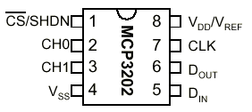
Connections

mcp3202s

Now moving to the spi registers in p89v51rd2 (8051)

3 registers:control register,configuration register,data register.

control register: enable spi,msb or lsb first,master mode, mode of the spi,and spi clock rate.

Since for mcp3202,the max freq is 1.8MHz. I’ve gone with dived by 16 option

My controller is working on a 11.0592MHz crystal oscillator.

11.0592MHz/16=0.692 Mhz which is less than 1.8MHz.

Configuration register:when the data is transferred successfully,the 8th bit is set & that is what we need to check for in the program.

data register:data to be sent & received is data register.

Back to MCP3202

What are the control bits to be sent to the adc?

start bit

single ended or pseudo differential

channel select

msbf

Before you send any data to the slave,make the chip select pin low.

I’ve used single ended,channel 0,MSBF=1

MCP3202D1

Now,when dealing with a 8 bit microcontroller in mode 0,0 go through the below diagram

mcp3202d2

1st data sent to slave: 0x01

Mcu receives: garbage value,discard it

2nd data sent to the slave: 0xa0

Mcu receives: highest nibble of the conversion (4bits)

3rd data sent to the slave: 0xff (any random value)

Mcu receives: next 8 bits

Therefore a total of 12 bits

Club the data together and send it to lcd or uart.

CODE:

#include<p89v51rd2.h>
#include<stdio.h>
sbit cs=P1^4;
sbit MOSI=P1^5; //din
sbit MISO=P1^6; //dout
sbit SCK=P1^7;

sfr info=0x80;
sbit rs=P2^0;
sbit rw=P2^1;
sbit en=P2^2;
void lcd_init();
void delay(unsigned int);
void lcdcmd(unsigned char);
void lcddata(unsigned char);
void str(char []);
void spi();
void convert(unsigned int,unsigned int);
int main()
{
unsigned char c,msb,lsb;
lcd_init();
lcddata(‘r’);
spi();

cs=1;
delay(1);
cs=0;
delay(2);

SPDAT=0x01; // start bit
while(SPCFG!=0x80);
SPCFG=0;
lcddata(‘s’);
c=SPDAT;

SPDAT=0xa0; // SGL/DIFF/MSBF

while(SPCFG!=0x80);
SPCFG=0;
lcddata(‘m’);
c=SPDAT;
if(c&0x10)
{
lcddata(‘n’);
}
msb=c&0x0f;

SPDAT=0xff;

while(SPCFG!=0x80);
SPCFG=0;
lcddata(‘e’);
lsb=SPDAT;

convert(msb,lsb);

cs=1;
while(1);

}
void spi()
{
SPCTL=0x51; // control register
}
void convert(unsigned int c1,unsigned int c2)
{
unsigned int i,c3,c4,a[4],b[4]={256,512,1024,2048};
float c5;
unsigned char x[20];
for(i=0;i<4;i++)
{
c3=c1>>i;
c3=c3&0x01;
a[i]=c3*b[i];
}
c4=a[0]+a[1]+a[2]+a[3];
c2=c2+c4;
// c5=(float)((c2*5000)/4096); // VALUE GOIN OUT OF RANGE
c5=100*c2;
c5=(float)(c5/4096);
c5=(float)(c5*50);
c5=(float)(c5/10);
sprintf(x,”%f”,c5);
str(x);

}
void lcd_init()
{
lcdcmd(0x80);
delay(250);
lcdcmd(0x38);
delay(250);
lcdcmd(0x0f);
delay(250);
lcdcmd(0x01);
delay(250);
lcdcmd(0x06);
delay(250);

}
void lcdcmd(unsigned char val)
{
info=val;
rs=0;
rw=0;
en=1;
delay(1);
en=0;
}
void lcddata(unsigned char value)
{
info=value;
rs=1;
rw=0;
en=1;
delay(1);
en=0;
}
void delay(unsigned int i)
{
unsigned int j,k;
for(j=0;j<i;j++)
for(k=0;k<1275;k++);
}
void str(unsigned char a[])
{
unsigned int i=0;
while(a[i]!=”)
{
lcddata(a[i]);
i++;
}
}

The sensor I’ve used is LM35 (Temperature sensor)