Learning Python is easy :)

8 Oct

If you don’t believe me check out this link on how to program using python.

Thank you ProgrammingKnowledge for making it so easy.

In the above video link,he uses windows operating system.

If you want to use Linux,

I am using Ubuntu,

1.Go to your terminal

2.Type python

If the python terminal opens with >>> ,then your in. Otherwise you have to install the python interpreter.

3. How to come out of python terminal?

  • exit()

4.How to create a python file?

Again go to your terminal

  • vim program.py
  • Type and save your program
  • To execute your program
    • python program.py

You’ll find your output on your terminal.

Enjoy Programming!!!


Embedasia – Home to the consortium for Embedded Systems

11 Aug

Centre for Embedded Intelligence (CFEI), as a professional IT group of people, aims to support continuous growth of Indian Economy through its technology and its personnel. CFEI focuses on innovative designs for Embedded products and solutions and also for core Embedded Systems Trainings & Conferences. CFEI is organizingEmbedasia during 19th & 20th September 2014 & this year’s theme will be on “Automotives and Avionics”.


The Embedasia 2014 Conference, delivered by the experts who design, build and support the products/services and consultants who specialize in deploying embedded system solutions, and the customers who use embedded system products each and every day.


There will be nearly 500 embedded system professionals including architects,  project managers and teams, IT managers and professionals, analysts and business decision makers coming together to learn, meet and to explore. The conference will offers prestigious key note lectures, technical speeches and interactive workshops.

Visit the link below,

http://embedasia.com/index.html

Device header files in Linux

11 Jun

When your entering into the world of drivers for example Linux,the first thing you’ll notice while writing the C program is the changed header files like
#include<linux/module.h>
#include<linux/serial_reg.h
#include<linux/init.h>
#include<linux/kernel.h>
etc…
They don’t exit in the C lib of the user space.
These header files exist in the kernel directory
The path is:
/usr/src/’uname -r’ (your kernel version)/include/linux

You’ll find all the above files in this directory 🙂
Eg:/usr/src/linux-2.4.20-8/include/linux

ARM7 to ARM7 (LPC2148) communication using I2C

1 Apr

     Board to board communication using I2C protocol, is simple once you’ve done any other program using this protocol with arm7. Since I have interfaced arm7 with eeprom. The same code used to send data to the eeprom is been used,except for the change in slave address,in this case it’s (0x00);

SEND

Master transmit mode

#include<lpc214x.h>
#include<stdio.h>
#include”appdef.h”
#include”armlcd.h”
#define led_port BIT0+BIT1+BIT8+BIT9+BIT25+BIT15+BIT12+BIT28
int c=1;
int r=0;
static int i=0;
unsigned char buf[12]=”YES YAMAHA”;
__irq void led(void)
{
     IOSET0=led_port;
     switch(I2C0STAT)
     {
         case 0x08 : lcd(‘s’); //start
                             I2C0CONCLR=BIT3+BIT5;

                             I2C0DAT=0x00;  //slave address of the other board

                             break;
          case 0x18 : lcd(‘a’);
                             I2C0CONCLR=BIT3;
                             break;
         case 0x28 : lcd(‘k’);
                            I2C0CONCLR=BIT3;
                            switch(c)
                            {
                               case 1 : I2C0DAT=buf[i];
                                             i++;
                                            if(i==10)
                                            {
                                                c++;
                                             }
                                             break;
                              case 2: I2C0CONSET=BIT4;
                                           lcd(‘p’);
                                           break;
                            }
                              break;
       case 0x30 : lcd(‘n’);
                          I2C0CONCLR=BIT3+BIT5;
                          break;
       default:      lcd(‘f’);
                         break;
}

VICVectAddr=0x00;
}

int main()
{

rs_clr();
en_clr();
lcd_init();
rs_set();
en_clr();
lcd(‘i’);
PINSEL0=BIT4+BIT6;

VICVectCntl0=0x29;
VICVectAddr0=(unsigned) led;
VICIntEnable=BIT9;

I2C0CONSET=BIT6;
I2C0CONCLR=BIT3+BIT2+BIT4;
I2C0SCLH=0x4B;
I2C0SCLL=0x4B;

I2C0CONSET|=BIT5;
while(1);

}
void lcd_init()
{
unsigned int i;
PINSEL0 = 0x00000000;

lcd_dir_write(); // output port
for (i=0;i<1000;i++);
lcd(0x33);
lcd(0x32);
lcd(0x28);
lcd(0x0e);
lcd(0x01);
lcd(0x06);
lcd(0x80);

for (i=0;i<1000000;i++);
}

void lcd(unsigned char val)
{
lcd1(val>>4);
lcd1(val);
}

void lcd1(unsigned char c)
{
unsigned int i;
IOCLR0 = 0x00f00000;
IOSET0 = (c<<20); // d4 connected to 20th port pin
en_set();
for (i=0;i<1000000;i++);
en_clr();
}

RECEIVE

Slight changes at the code at the slave side.You have to choose the arm controller to be in slave mode.

Slave receiver mode.

I2C0ADR=0X01; // general call address.Only when you set bit0 of this register can the master board send address as 0x00 to the slave board.

Enable bit & AA bit of the I2CCONSET register has to set to 1 during initialization. 

Remember no start bit required.

status codes are 0x70,0x90. go through the user manual

#include<lpc214x.h>
#include<stdio.h>
#include”appdef.h”
#include”armlcd.h”
#define led_port BIT0+BIT1+BIT8+BIT9+BIT25+BIT15+BIT12+BIT28
int c=0;
int r=0,dw=1,ss=0,rs=0,j;
char ch;
__irq void led(void)
{
        switch(I2C0STAT)
       {
           case 0x70 : lcd(‘g’);  
                              I2C0CONSET|=BIT2;  //AA bit set
                              I2C0CONCLR=BIT3;
                              break;
           case 0x90 :ch=I2C0DAT;  //data received and stored safely
                             I2C0CONCLR=BIT3;
                             lcd(ch);
                             break;
           case 0xa0 :lcd(‘p’);
                             I2C0CONCLR=BIT3;
                             break;
           default:lcd(‘f’);
                       I2C0CONCLR=BIT3;
                       break;
}

VICVectAddr=0x00;
}

int main()
{

rs_clr();
en_clr();
lcd_init();
rs_set();
en_clr();
PINSEL0=BIT4+BIT6;
VICVectCntl0=0x29;
VICVectAddr0=(unsigned) led;
VICIntEnable=BIT9;

I2C0ADR=0X01;  // general call addr
I2C0CONSET=BIT6+BIT2; // SLAVE MODE
I2C0CONCLR=BIT3;
I2C0SCLH=0x4B;
I2C0SCLL=0x4B;

lcd(‘v’);
while(1);
}
void lcd_init()
{
unsigned int i;
PINSEL0 = 0x00000000;

lcd_dir_write(); // output port
for (i=0;i<1000;i++);
lcd(0x33);
lcd(0x32);
lcd(0x28);
lcd(0x0e);
lcd(0x01);
lcd(0x06);
lcd(0x80);

for (i=0;i<1000000;i++);
}

void lcd(unsigned char val)
{
lcd1(val>>4);
lcd1(val);
}

void lcd1(unsigned char c)
{
unsigned int i;
IOCLR0 = 0x00f00000;
IOSET0 = (c<<20); // d4 connected to 20th port pin
en_set();
for (i=0;i<1000000;i++);
en_clr();
}

SPI Protocol,Interfacing MCP3202 with 8051 (NXP Philips P89V51RD2)

27 Mar

The clock polarity and clock phase is used for the shift registers used at master and slave end to shift the data in or out more reliably.

Make an effort to go through the data sheet and also the link provided if your dealing with shift registers which is normally present when dealing with a spi interface.

http://www.allaboutcircuits.com/vol_4/chpt_12/2.html

While going through spi protocol,you’ll come across 4 modes,now the question is which mode to select for the project.Well,it depends on the slave device.In the data sheet,the modes to use will be mentioned mostly in the 1st page of the data sheet itself.

Next is the frequency selection,you have to look into the electrical characteristics of the slave device to know what is the fosc (frequency) which is important for data transfer using spi protocol.

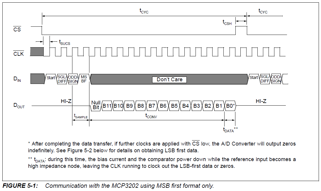
For MCP3202,it’s mentioned 100ksps or 5oksps. ksps means kilo samples per sec that adc takes to process.

fsample =100ksps, therefore,fclk=18*fsample

fclk=18*100K=1.8MHz. This the max frequency allowed for 100ksps.

Connections

mcp3202s

Now moving to the spi registers in p89v51rd2 (8051)

3 registers:control register,configuration register,data register.

control register: enable spi,msb or lsb first,master mode, mode of the spi,and spi clock rate.

Since for mcp3202,the max freq is 1.8MHz. I’ve gone with dived by 16 option

My controller is working on a 11.0592MHz crystal oscillator.

11.0592MHz/16=0.692 Mhz which is less than 1.8MHz.

Configuration register:when the data is transferred successfully,the 8th bit is set & that is what we need to check for in the program.

data register:data to be sent & received is data register.

Back to MCP3202

What are the control bits to be sent to the adc?

start bit

single ended or pseudo differential

channel select

msbf

Before you send any data to the slave,make the chip select pin low.

I’ve used single ended,channel 0,MSBF=1

MCP3202D1

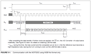
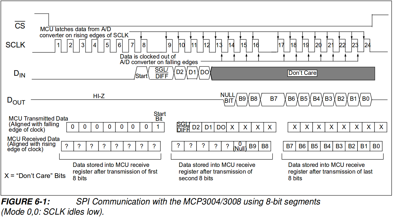
Now,when dealing with a 8 bit microcontroller in mode 0,0 go through the below diagram

mcp3202d2

1st data sent to slave: 0x01

Mcu receives: garbage value,discard it

2nd data sent to the slave: 0xa0

Mcu receives: highest nibble of the conversion (4bits)

3rd data sent to the slave: 0xff (any random value)

Mcu receives: next 8 bits

Therefore a total of 12 bits

Club the data together and send it to lcd or uart.

CODE:

#include<p89v51rd2.h>
#include<stdio.h>
sbit cs=P1^4;
sbit MOSI=P1^5; //din
sbit MISO=P1^6; //dout
sbit SCK=P1^7;

sfr info=0x80;
sbit rs=P2^0;
sbit rw=P2^1;
sbit en=P2^2;
void lcd_init();
void delay(unsigned int);
void lcdcmd(unsigned char);
void lcddata(unsigned char);
void str(char []);
void spi();
void convert(unsigned int,unsigned int);
int main()
{
unsigned char c,msb,lsb;
lcd_init();
lcddata(‘r’);
spi();

cs=1;
delay(1);
cs=0;
delay(2);

SPDAT=0x01; // start bit
while(SPCFG!=0x80);
SPCFG=0;
lcddata(‘s’);
c=SPDAT;

SPDAT=0xa0; // SGL/DIFF/MSBF

while(SPCFG!=0x80);
SPCFG=0;
lcddata(‘m’);
c=SPDAT;
if(c&0x10)
{
lcddata(‘n’);
}
msb=c&0x0f;

SPDAT=0xff;

while(SPCFG!=0x80);
SPCFG=0;
lcddata(‘e’);
lsb=SPDAT;

convert(msb,lsb);

cs=1;
while(1);

}
void spi()
{
SPCTL=0x51; // control register
}
void convert(unsigned int c1,unsigned int c2)
{
unsigned int i,c3,c4,a[4],b[4]={256,512,1024,2048};
float c5;
unsigned char x[20];
for(i=0;i<4;i++)
{
c3=c1>>i;
c3=c3&0x01;
a[i]=c3*b[i];
}
c4=a[0]+a[1]+a[2]+a[3];
c2=c2+c4;
// c5=(float)((c2*5000)/4096); // VALUE GOIN OUT OF RANGE
c5=100*c2;
c5=(float)(c5/4096);
c5=(float)(c5*50);
c5=(float)(c5/10);
sprintf(x,”%f”,c5);
str(x);

}
void lcd_init()
{
lcdcmd(0x80);
delay(250);
lcdcmd(0x38);
delay(250);
lcdcmd(0x0f);
delay(250);
lcdcmd(0x01);
delay(250);
lcdcmd(0x06);
delay(250);

}
void lcdcmd(unsigned char val)
{
info=val;
rs=0;
rw=0;
en=1;
delay(1);
en=0;
}
void lcddata(unsigned char value)
{
info=value;
rs=1;
rw=0;
en=1;
delay(1);
en=0;
}
void delay(unsigned int i)
{
unsigned int j,k;
for(j=0;j<i;j++)
for(k=0;k<1275;k++);
}
void str(unsigned char a[])
{
unsigned int i=0;
while(a[i]!=”)
{
lcddata(a[i]);
i++;
}
}

The sensor I’ve used is LM35 (Temperature sensor)

Interfacing external memory with LPC2148 using I2C Protocol (PART 2)

14 Mar

Dummy write operation

So once your done with writing data into the EEPROM,you would want to read from the location where you have written into.Image

The diagram above clearly shows the steps how it needs to be done. 

CODE:

#include<lpc214x.h> // standard header file
#include”appdef.h” // defining bits,example:#define BIT0 0x01<<0
#include”armlcd.h” // initialisations for lcd
#define led_port BIT0+BIT1+BIT8+BIT9+BIT25+BIT15+BIT12+BIT28
int c=0;
int r=0,dw=1,ss=0,rs=0,j;
char ch;
__irq void led(void)
{
switch(I2C0STAT)
{
case 0x08 : //lcd(‘s’); // 1.start
                  I2C0CONCLR=BIT3; 
                  I2C0DAT=0xa0; // dummy write
                  break;
case 0x10 :// lcd(‘b’); // 4. repeated start condition status
                   I2C0CONCLR=BIT3+BIT5;
                  I2C0DAT=0xa1; // read
                  break;
case 0x18 : //lcd(‘a’); // 2. write  ack
                   I2C0CONCLR=BIT3+BIT5;
                   I2C0DAT=0x00; // memory address
                   break;
case 0x28 : //lcd(‘k’); // 3. ack
                   I2C0CONCLR=BIT3;
                   I2C0CONSET|=BIT5; // repeated start bit
                   break;
case 0x40 : //lcd(‘r’);  // 5.read ack
                   I2C0CONCLR=BIT3;
                   I2C0CONSET=BIT2; // aa flag
                   break;
case 0x48 : lcd(‘l’);
                   I2C0CONCLR=BIT3;
                   break;
case 0x50 : I2C0CONCLR=BIT3; // 6.start receiving data
                   ch=I2C0DAT;
                   lcd(ch);
                  if(dw==9)
                  {
                       I2C0CONCLR=BIT2;  // sending a no ack after reading 10 bytes
                  }
                  dw++;
                  break;
case 0x58 ://lcd(‘n’);   // 7.stop bit
                   I2C0CONCLR=BIT3;
                   I2C0CONSET=BIT4;
                   break;
default:lcd(‘f’);
             I2C0CONCLR=BIT3;
              break;
}

VICVectAddr=0x00;
}

int main()
{

rs_clr();
en_clr();
lcd_init();
rs_set();
en_clr();
//lcd(‘i’);
PINSEL0=BIT4+BIT6;
VICVectCntl0=0x29;
VICVectAddr0=(unsigned) led;
VICIntEnable=BIT9;

I2C0CONSET=BIT6;
I2C0CONCLR=BIT3;
I2C0SCLH=0x4B;
I2C0SCLL=0x4B;

I2C0CONSET|=BIT5; //start
while(1);
}
void lcd_init()
{
unsigned int i;
PINSEL0 = 0x00000000;

lcd_dir_write(); // output port
for (i=0;i<1000;i++);
lcd(0x33);
lcd(0x32);
lcd(0x28);
lcd(0x0e);
lcd(0x01);
lcd(0x06);
lcd(0x80);

for (i=0;i<1000000;i++);
}

void lcd(unsigned char val)
{
lcd1(val>>4);
lcd1(val);
}

void lcd1(unsigned char c)
{
unsigned int i;
IOCLR0 = 0x00f00000;
IOSET0 = (c<<20); // d4 connected to 20th port pin
en_set();
for (i=0;i<1000000;i++);
en_clr();

}

Interfacing external memory with LPC2148 using I2C Protocol

10 Mar

I am using a LPC2148 development board from NSK Electronics. It has a slot for inserting external memory,I’ve used 24C02 chip.

LPC2148 has an inbuilt module for i2c protocol. All we need to know is how to use these registers.But before you dive into i2c of arm7,you need to learn to program for lpc2148 interrupts.Any interrupt as a matter of fact,because the i2c interrupt generation is very crucial.

Check out the below link  to learn more on interrupts in lpc2148

LPC2148 Interrupt Tutorial

The registers used for i2c are

I2C0CONSET,I2C0CONCLR,I2C0STAT,I2C0DAT

I2C0SCLH & I2C0SCLL used to set the bit frequency. The Pclk clock value I’ve taken is 15MHz.

LPC2148 is the master when writing into EEPROM and when it is reading.

Therefore Master transmit & receive mode.

The I2C0STAT register will tell you the status of the i2c module in arm,on when the interrupt flag SI is set. otherwise it will give you a value 0xf8. Therefore you can read the status only in the ISR which you have written for i2c interrupt.The SI flag gets SET automatically each time and it’s very important to clear the flag each time you enter the ISR.

Don not set all the bits in I2C0CONSET,I2C0CONCLR at one short.Go according to the steps required for i2c communication.

write-i2c

Writing into EEPROM

#include<lpc214x.h>
#include<stdio.h>
#include”appdef.h”
#include”armlcd.h”

int c=1;

static int i=0;
unsigned char buf[12]=”YES YAMAHA”;
__irq void led(void)
{
switch(I2C0STAT)
{
case 0x08 : lcd(‘s’); //start
I2C0CONCLR=BIT3+BIT5;  // clr start & SI bit
I2C0DAT=0xa0;  //device address
break;

case 0x10 : lcd(‘b’);
I2C0CONCLR=BIT3;  // clearing SIbit
break;

case 0x18 : lcd(‘a’);
I2C0CONCLR=BIT3;
I2C0DAT=0x00; // memory address
break;
case 0x28 : lcd(‘k’);
I2C0CONCLR=BIT3;
switch(c)
{
case 1 :
I2C0DAT=buf[i];  // writing data into EEPROM
lcd(‘m’);
i++;
if(i==10) //10 characters
{
c++;
}
break;

case 2: I2C0CONSET=BIT4; // stop bit
lcd(‘p’);
break;

}

break;
case 0x30 : lcd(‘n’);
I2C0CONCLR=BIT3+BIT5;
break;

default: lcd(‘f’);
break;
}

VICVectAddr=0x00;
}

int main()
{
rs_clr();
en_clr();
lcd_init();
rs_set();
en_clr();
lcd(‘i’);
PINSEL0=BIT4+BIT6;  // scl & sda pin
VICVectCntl0=0x29;
VICVectAddr0=(unsigned) led;
VICIntEnable=BIT9;

I2C0CONSET=BIT6;
I2C0CONCLR=BIT3+BIT2+BIT4;
I2C0SCLH=0x4B;   //100 MHz bit freq
I2C0SCLL=0x4B;

I2C0CONSET|=BIT5;  //start bit

}
void lcd_init()
{
unsigned int i;
PINSEL0 = 0x00000000;

lcd_dir_write(); // output port
for (i=0;i<1000;i++);
lcd(0x33);
lcd(0x32);
lcd(0x28);
lcd(0x0e);
lcd(0x01);
lcd(0x06);
lcd(0x80);

for (i=0;i<1000000;i++);
}

void lcd(unsigned char val)
{
lcd1(val>>4);
lcd1(val);
}

void lcd1(unsigned char c)
{
unsigned int i;
IOCLR0 = 0x00f00000;
IOSET0 = (c<<20); // d4 connected to 20th port pin
en_set();
for (i=0;i<1000000;i++);
en_clr();
}

I’ve used lcd in 4bit mode to display my output. At certain places I have passed character to lcd function,just to check for the proper functioning.Helps in debugging.You can take it off,if you want.

Software used:keil and philips utility

The future of connectivity & automotive intelligence

16 Jan

Links to videos form Freescale,which I found it pretty cool,Especially the automotive video. Enjoy!

http://www.electronicsweekly.com/video/miscellaneous/the-era-of-connected-intelligence-networking-2011-03/

http://www.electronicsweekly.com/video/miscellaneous/the-era-of-connected-intelligence-automotive-2011-03/

Linux & embedded

27 Nov

Operating systems being an optional subject for electronics student in India in some universities.Very few have a knowledge on operating system,let alone Linux.
Text books seem to talking about everything else other the use of linux in embedded systems.One can consider text books to learn the APIs or system calls of linux well.The below link posted will give you a idea about what all you would come across while starting to learn Linux.
http://www.embedded.com/electronics-blogs/open-mike/4420567/Learning-Linux-for-embedded-systems

The change return program

21 Sep

Change Return Program – The user enters a cost and then the amount of money given. The program will figure out the change in Rs notes of 1000,500,100,50,10,1’s and paise.

#include<stdio.h>

void change(int,int,int,int,int,int,double);

int main()

{

      double amt,cash,bal;

      int th=0,fhd=0,hd=0,fifty=0,tens=0,ones=0;int notes,cnt=0,n1,i;

       printf(“enter the amount\n”);

       scanf(“%lf”,&amt);

       printf(“enter the cash recieved\n”);

       scanf(“%lf”,&cash);

      bal=cash-amt;

      printf(“change=%lf\n”,bal);

      notes=bal;

      bal=bal-notes;

     while(notes!=0)

     {

             n1=notes%10;

            if(cnt==0)

          {

                  i=0;

                  while(n1!=i)

                           i++;

                  ones=i;

        }

        elseif(cnt==1)

       {

              i=0;

              while(n1!=i)

              i++;

             if(i>=5 && i<=9)

            {

                  fifty++;

                  tens=i-5;

            }

           else

                tens=i;

         }

        elseif(cnt==2)

       {

            i=0;

            while(n1!=i)

                       i++;

           if(i>=5 && i<=9)

         {

                  fhd++;

              hd=i-5;

          }

        else

          hd=i;

        }

        elseif(cnt==3)

       {

            i=0;

             while(n1!=i)

                     i++;

             th=i;

        }

    notes=notes/10;

   cnt++;


  }

     change(th,fhd,hd,fifty,tens,ones,bal);

    return 0;

}

void change(int t,int fh,int hd,int fifty,int tens,int ones,doublep)

{

        if(t)

        printf(“1000 rs – %d\n”,t);if(fh)

        printf(“\t500 rs – %d\n”,fh);if(hd)

        printf(“\t100 rs – %d\n”,hd);if(fifty)

         printf(“\t50 rs – %d\n”,fifty);if(tens)

       printf(“\t10 rs – %d\n”,tens);if(ones)

        printf(“\t1 rupee – %d\n”,ones);if(p)

       printf(“\tpaise – %lf\n”,p);

}